A saw blade is a good way to explain edge measurement, because counting its teeth looks trivial and is not. You can see the teeth. A vision system cannot: it has a grid of intensities, and everything you want to know has to come out of where those intensities change.
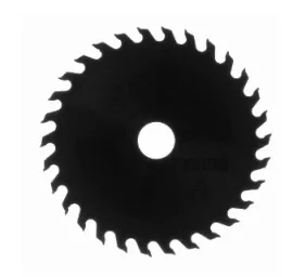
Every number below comes from the arbor hole and one circle drawn through the teeth.
Do not count the teeth — measure across them
The instinct is to find the blade’s outline and count the bumps on it. That means separating blade from background, which means picking a threshold, and a threshold is a promise about the lighting that you will not be able to keep.
The better move is to segment nothing. Put a circle on the image, centred on the arbor hole, at a radius that passes through every tooth, and read the image along that circle. A closed path through all the teeth turns a two-dimensional counting problem into a one-dimensional signal with one feature per tooth.
That is the actual idea, and the rest is consequences of it. A signal that should be periodic is a signal you can check, and being able to check the answer is worth more than getting it.
The origin comes from the part, not from the image
The circle needs a centre, and the centre has to be a feature of the blade rather than a position in the frame. The arbor hole is the obvious candidate: fit a circle to it and every measurement afterwards is expressed relative to the part.
This is what makes the method survive contact with a real cell. The blade is never placed the same way twice. If the origin travels with the blade, that stops being a problem instead of becoming a calibration ritual.
Stripes, not edges
An edge is a single transition. A stripe is a pair of them — a rising edge and a falling edge, of a stated polarity, with a width between them.
Counting stripes rather than edges is the whole reliability argument. An edge is a place where the intensity moved, and plenty of things move it: a glint on ground steel, a scratch, the seam of the background. A stripe additionally has a width, and a width is something you can reject on. Noise readily produces one transition. It much less readily produces a matched pair of the right polarity, of roughly the right width, at roughly the right spacing.
So the parameters that matter are the ones that describe the tooth as an object: polarity, taken from which way the tooth is darker than what surrounds it; a width range, taken from the blade specification rather than from the image; and a contrast threshold set high enough that a soft gradient is not allowed to be a tooth. Edge positions themselves come out at sub-pixel precision from the shape of the intensity gradient, which is why this is a measurement rather than a pixel count.
The check that costs nothing
If the count is right, the teeth are evenly spaced in angle. That is not an extra requirement — it is a property of the part you are already holding, and it is free.
Convert each detected stripe to an angle about the centre, take the gaps between consecutive angles, and look at their spread. Uniform gaps mean you counted teeth. One gap at twice the others means you missed one, and the gap tells you exactly where to look. Gaps at half the spacing mean you counted something twice.
This is the difference between a number and a measurement. A system that reports 71 teeth is useless, because nobody can tell whether it is right. A system that reports 72 and can say the angular spacing was uniform to within a fraction of a degree has actually measured something, and can be trusted to say when it should not be.
What actually breaks
Three things, in my experience, and none of them is the algorithm.
Reflection. Ground steel is close to a mirror. A specular highlight crossing the scan path is high-contrast and looks exactly like the transition you are hunting for. This is a lighting problem and it is solved with lighting — diffuse, off-axis — not by lowering a threshold until the highlight goes away, which also removes the teeth.
Teeth that are not identical. Many blades are ground with an alternate top bevel, so consecutive teeth are angled opposite ways and do not present the same face to the camera. Anything that assumes every tooth looks like the last one will find half of them. The width tolerance has to cover both appearances, and the periodicity check has to expect one tooth per gap rather than one bevel.
The radius. Too close to the hub and the path passes inside the tooth roots and sees nothing. Too far and it leaves the blade between teeth and the signal becomes background. It wants to sit where the teeth are widest, and it is worth deriving it from the detected hole radius rather than fixing it, so that one recipe covers a family of blade sizes.
Where this generalises
Nothing above is about saw blades. The method is: find a feature on the part that defines a coordinate system, scan a path the features of interest must cross, measure pairs rather than transitions, and verify the result against the regularity you already expect.
That applies to gear teeth, holes in a perforated sheet, splines on a shaft, threads, connector pins — anything repetitive arranged around something you can locate. The part changes and the recipe does not.
Here is the whole thing running on the blade at the top of this article:
The one thing I would carry out of this into any measurement problem is the last section rather than the first. Getting the count is ordinary work. Being able to say why the count is right, from evidence in the same image, is what separates a demo from something you can put in front of a machine that acts on the answer.